

Please Leave Us A Message
Privacy statement: Your privacy is very important to Us. Our company promises not to disclose your personal information to any external company with out your explicit permission.
 Xi'an Heaven Abundant Mining Equipment CO.,LTD
A TCI (Tungsten Carbide insert) tricone bit is one of the most widely used rock drilling tools in the oil and gas, water well, and mining industries. Its ability to crush hard formations through a combination of rotating cones and extremely hard carbide inserts makes it indispensable for deep drilling operations. But how exactly is a TCI tricone bit manufactured? The process involves precision engineering, metallurgical expertise, and rigorous quality control at every stage. Below is a detailed breakdown of each step.
Every tricone bit begins with a digital design tailored to the specific drilling conditions it will face. Engineers use CAD (Computer-Aided Design) software to model the bit body, cone geometry, bearing arrangement, and insert placement. The IADC (International Association of Drilling Contractors) classification system guides this process—determining which bit type, cutting structure, and bearing configuration will perform best in the target formation.
Key design variables include the number of rows of inserts, the offset angle of the cones relative to the bit center, the journal angle, and the hydraulic nozzle layout. These factors directly influence the bit's rate of penetration (ROP), durability, and steering behavior. For soft formations, longer and more widely spaced inserts with aggressive cone offset are used to maximize scraping action. For hard formations, shorter, more closely packed inserts with minimal offset deliver a crushing and chipping action. Sophisticated simulation software can now predict drilling performance, helping engineers optimize the design before a single piece of steel is cut.
The quality of a tricone bit starts with the quality of its raw materials. Three primary material categories are involved:
Every batch of incoming steel and carbide undergoes spectrographic analysis and mechanical testing to verify its chemical composition and physical properties before entering production.
The bit legs and cones begin as forged blanks. The alloy steel billets are heated to approximately 1,150–1,200°C and forged under high pressure to achieve the near-net shape of each component. Forging aligns the grain structure of the steel, giving it superior strength and fatigue resistance compared to cast or machined-from-solid alternatives.
After forging, the components undergo a carefully controlled heat treatment cycle. The process typically includes:
Heat treatment parameters—temperature, soak time, and cooling rate—are documented for every batch and must meet strict specifications, as they directly determine the steel's final mechanical properties and the bit's service life.
Once heat-treated, the components move to CNC (Computer Numerical Control) machining centers. This stage transforms the forged blanks into precisely dimensioned parts. Key machining operations include:
Coordinate measuring machines (CMMs) verify all critical dimensions after machining, ensuring they meet API and ISO 9001 quality standards.
The most vulnerable areas of the bit body—particularly the shirttail, the back of the legs, and the gauge surfaces—are protected with a layer of hardfacing alloy. This is applied through advanced welding techniques, such as plasma transferred arc (PTA) welding or oxy-acetylene welding with a tungsten carbide composite rod.
The hardfacing material typically contains crushed tungsten carbide particles suspended in a nickel-based or iron-based matrix. When applied, the matrix melts and bonds to the steel substrate while the carbide particles remain intact, creating a surface with exceptional abrasion resistance. The IADC classification system notes hardfacing features with designations such as "G" for gauge protection and "D" for specialized shirttail protection. Proper hardfacing significantly extends a bit's operating life in abrasive formations, making it a critical quality step.
For TCI bits, the tungsten carbide inserts are the defining cutting element. Holes are drilled into the cone bodies at precisely calculated positions and angles, with diameters slightly smaller than the insert shanks. The inserts are then pressed in using a hydraulic press that applies thousands of pounds of force, creating an interference fit that mechanically locks each insert in place.
The shape and grade of each insert are selected based on its position on the cone and the target formation:
After pressing, each insert is checked for proper protrusion height and alignment. Any insert that is not seated correctly is rejected, as a loose insert in operation can cause catastrophic bit failure.
The bearing system is the heart of a tricone bit's reliability. Two main types are used in TCI bits:
During assembly, the bearings are installed onto the journal pin, and the cone is carefully placed over the assembly. Ball bearings are then loaded through a loading hole to secure the cone axially. A plug is welded into the loading hole to lock everything in place. The assembled cone must rotate freely with minimal play—any binding or excessive clearance is cause for rejection.
A reliable lubrication system is essential for sealed bearing bits. Each leg contains a machined grease reservoir connected to the bearing cavity by small channels. During assembly, the reservoir is filled with a specialized high-temperature, extreme-pressure grease formulated to maintain its lubricating properties at downhole temperatures exceeding 150°C.
A pressure compensation diaphragm or piston is installed in the reservoir. This flexible component equalizes the internal grease pressure with the external hydrostatic pressure of the drilling fluid column, which can reach thousands of PSI at depth. Without this compensation, the pressure differential would rupture the seals and allow drilling fluid to contaminate the bearings. The integrity of the lubrication system is pressure-tested before the bit moves to final assembly.
With all three leg-and-cone assemblies complete and verified, the final step is joining them together to form the complete bit. The three legs are precisely aligned in a welding fixture and joined using a multi-pass welding process. The root pass penetrates deep into the joint, and subsequent passes build up the weld to full strength. The welding is typically performed by automated robotic systems to ensure consistent quality and penetration.
After welding, the weld area is inspected for defects using magnetic particle or ultrasonic testing. The threaded connection is checked with a go/no-go gauge to ensure it meets API dimensional standards. The bit is then cleaned, painted, and marked with the IADC code, serial number, size, and manufacturer identification. A final visual inspection verifies that all markings are legible and correctly positioned.
Before a TCI tricone bit is approved for shipment, it must pass a comprehensive quality control program. At a minimum, every bit undergoes:
Manufacturers with ISO 9001 certification, such as Xi'an Heaven Abundant Mining Equipment CO.,LTD (TY Drill Bits), follow documented quality procedures and maintain full traceability records for every component and production batch. This ensures that each bit can be traced back to its raw material origins and manufacturing parameters.
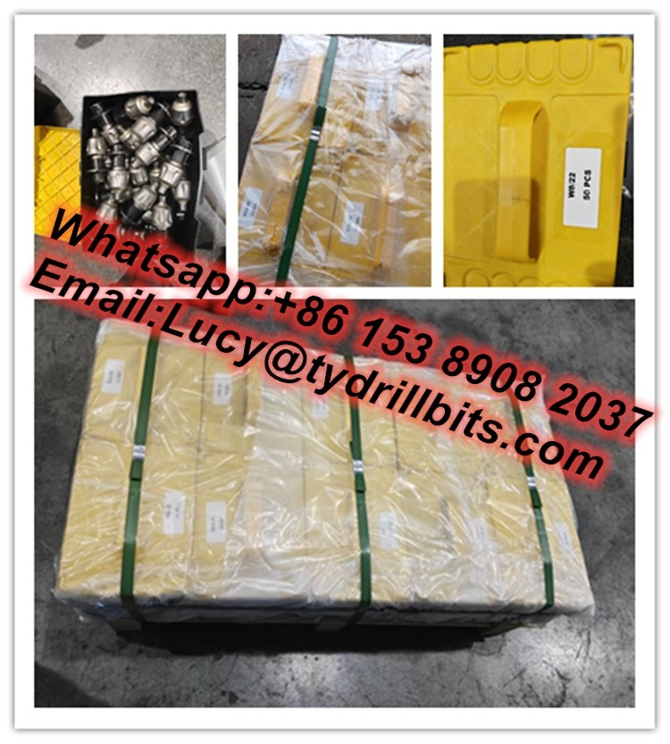
Approved bits are coated with a rust-preventive compound, and the threads are fitted with protective caps. Each bit is packaged in a sturdy wooden crate or steel frame designed to protect it during transportation. The packaging includes the bit's documentation package—certificate of conformance, inspection report, and operating recommendations.
For international buyers, reliable tricone bit wholesale suppliers offer flexible shipping terms including FOB, CIF, and EXW, with typical lead times of 15 working days. Buyers should verify that the manufacturer provides full quality documentation, offers OEM customization services, and can supply a range of sizes—from 3-inch to 12-1/4-inch and beyond—to meet diverse drilling requirements.
Conclusion
Manufacturing a TCI tricone bit combines metallurgical science, precision machining, and rigorous quality control at every step. From the initial CAD design and alloy steel selection to the final weld inspection and packaging, each stage is engineered to produce a tool that can endure the extreme conditions encountered deep underground. Understanding this process helps drilling professionals appreciate why quality manufacturing matters—and why choosing a reputable TCI tricone bit supplier with proven expertise and ISO-certified processes is essential for safe, efficient, and cost-effective drilling operations.
Email to this supplier
About Us
Products
Contact Us

Privacy statement: Your privacy is very important to Us. Our company promises not to disclose your personal information to any external company with out your explicit permission.
Fill in more information so that we can get in touch with you faster
Privacy statement: Your privacy is very important to Us. Our company promises not to disclose your personal information to any external company with out your explicit permission.